[Wuzhong Zhongchuang Self-Control Valve Co., Ltd.] Detailed Illustrated Explanation of Globe Valves
【Wuzhong Zhongchuang Self-Control Valve Co., Ltd.】Globe valve, also called stop valve, is a very widely used type of valve. During the opening and closing process, the friction force between the sealing surfaces is small, making it relatively durable. The opening height is not large, it is easy to manufacture and convenient to maintain. It is suitable not only for medium and low pressure, but also for high pressure.
Working Principle of Globe Valve
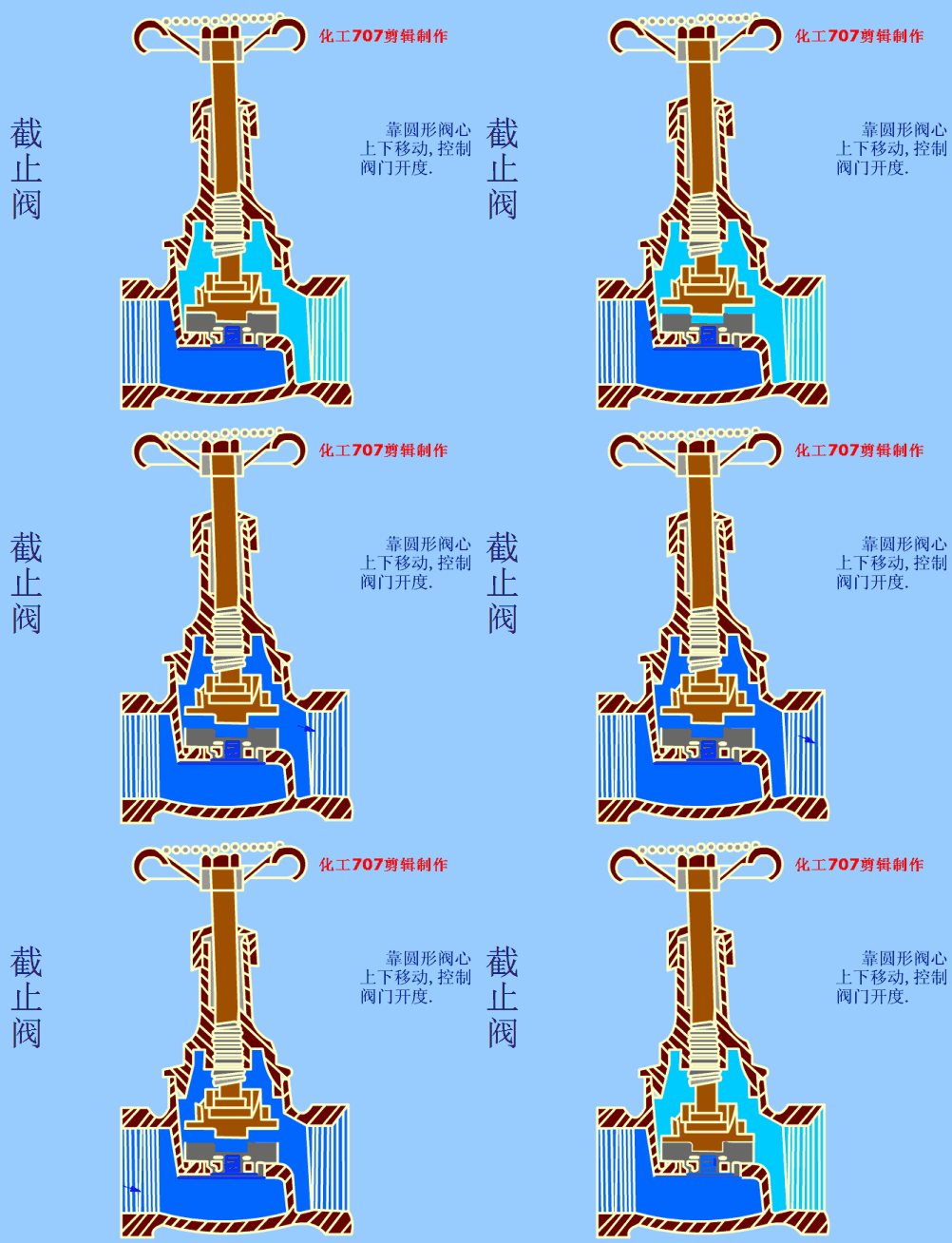
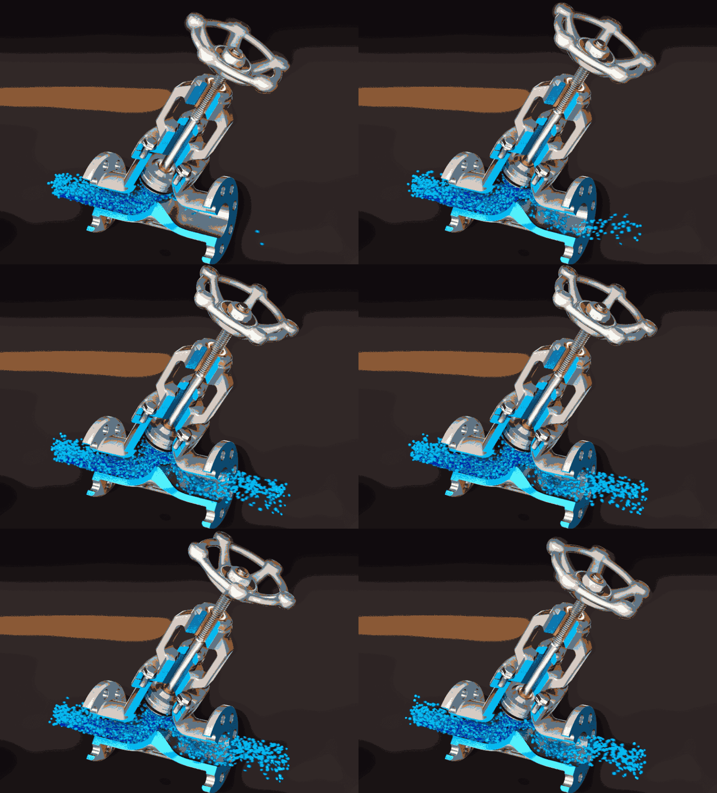
The opening and closing part of a globe valve is a plug-shaped valve disc. The sealing surface is flat or conical, and the valve disc moves in a straight line along the centerline of the fluid.
The closing principle of a globe valve is that it relies on valve stem pressure to make the valve disc sealing surface and the valve seat sealing surface fit tightly together, preventing medium flow.
Globe valves only allow medium to flow in one direction and have directionality during installation. The structural length of a globe valve is greater than that of a gate valve, and at the same time, the fluid resistance is greater. During long-term operation, the sealing reliability is not strong.
Classification of Globe Valves
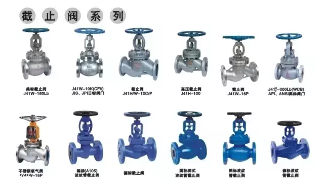
Classification by Channel Direction
01
Straight-Through Globe Valve
The medium inlet and outlet channels are in the same direction at 180°. The degree of flow state destruction is relatively small, and the pressure loss through the valve is relatively small.
02
Y-Pattern Globe Valve
The valve stem and channel form a certain angle, and the valve seat sealing surface and the inlet and outlet channels have a certain angle. The fluid hardly changes flow direction, making it the globe valve with the smallest flow resistance. Suitable for pipelines with coking and solid particles.
03
Angle Globe Valve
The medium inlet and outlet channels are not in the same direction, forming a 90° angle, which will produce a certain pressure drop. The biggest advantage is that it can be installed at the turning point of the pipeline system, saving elbows and facilitating operation.
Classification by Thread Position on Screw Rod
01
Outside Screw and Yoke Globe Valve
The valve stem thread is on the outside of the body, not in direct contact with the working medium. The valve stem thread is not subject to medium corrosion, easy to lubricate, and labor-saving to operate.
02
Lower Thread Valve Stem Globe Valve
The valve stem thread is inside the valve body, in direct contact with the working medium. The valve stem thread is susceptible to medium corrosion and cannot be lubricated. It is mostly used in applications with smaller nominal diameters and lower medium working temperatures.
Classification by Application
01
Fluorine-Lined Globe Valve
Fluorine-lined valves, also known as fluoroplastic-lined corrosion-resistant valves, are made by placing polytetrafluoroethylene resin (or processed profiles) on the inner wall of steel or iron valve pressure-bearing parts (the same method applies to the lining of various pressure vessels and piping accessories) or the outer surface of valve internals using compression molding (or inlay) methods, utilizing their unique performance in resisting strong corrosive media to manufacture various valves and pressure vessels.
Fluorine-lined globe valves are suitable for use in pipelines with aqua regia, sulfuric acid, hydrochloric acid, hydrofluoric acid and various organic acids, strong acids, strong oxidants of various concentrations at -50~150℃, and are also suitable for strong alkaline organic solvents of various concentrations and other corrosive gases and liquid media.
02
National Standard Globe Valve
National standard globe valves are the most commonly used products in the globe valve series. API American standard globe valves comply with ANSI and API standards. The sealing surfaces of the valve disc and valve seat are hardfaced with Stellite cobalt-based hard alloy of different hardness, featuring reliable sealing, high hardness, wear resistance, high temperature resistance, corrosion resistance, excellent scratch resistance, and long service life.
03
Needle Valve
Needle valves are small-diameter instrument valves that play a role in opening, closing, and precise flow control in instrument measurement piping systems. Main types include power station instrument series, oilfield special series, American standard series, etc.
04
Cryogenic Globe Valve
Cryogenic globe valves typically refer to valves with working temperatures below -110℃, widely used in liquefied natural gas, liquefied petroleum gas, and other cryogenic industries.
Currently, globe valves suitable for temperatures down to -196℃ can be manufactured. **Components are subjected to cryogenic pre-treatment with liquid nitrogen** to avoid seal deformation and leakage during use.
05
Plunger Globe Valve
Plunger valve, also known as plunger globe valve, adopts a radial sealing structure for its sealing surface. Two elastic sealing rings fitted on the polished plunger are compressed around the plunger by the load applied to the valve bonnet through the connecting bolts between the valve body and bonnet to achieve sealing.
06
Jacketed Globe Valve
Jacketed globe valves adopt a thermal jacket design, utilizing external heat sources to circulate heating around the exterior of the valve, which can effectively prevent temperature loss of the medium when passing through the valve and maintain the medium's temperature.
07
Oxygen Service Globe Valve
Oxygen service globe valves are cast from high-quality silicon brass or stainless steel, featuring advantages such as high mechanical strength, wear resistance, and good safety performance.
Used in oxygen pipelines, they possess **excellent explosion-proof and flame-retardant performance**, eliminating unsafe factors in oxygen pipelines, and are widely applied in pipeline networks for oxygen engineering in steel, metallurgy, petrochemical, chemical and other industries. In addition to the functions of ordinary valves, they also have their own characteristics.
Strict oil-free measures are adopted during manufacturing, and all parts undergo strict degreasing treatment before installation.
08
Bellows Globe Valve
The bellows globe valve adopts a formed stainless steel bellows design. The bellows has been tested 10000 times without failure. The sealing performance is reliable and is suitable for industrial and mining applications with flammable, explosive, toxic and harmful media, which can effectively prevent valve external leakage.
Storage, Transportation and Installation of Globe Valves
◆ ◆ ◆
Storage and Transportation of Globe Valves
Shipping Preparation
The valve packaging should prevent any damage to the valve during transportation and storage. The following points should be noted:

When packaging, the valve disc should be in the closed position.

Valve flange sealing surfaces/welding bevels/threaded ends should be coated with suitable protective grease (except for stainless steel materials). Both ends of the valve should be reliably fixed with wooden, wood fiber or plastic end caps to protect the connection end surfaces and the valve interior.
When packaging electric actuator valves, care must be taken to secure them safely to ensure that the electric actuator will not be damaged and will not penetrate through the wooden box/crate.

The packaging type should be clearly specified in the order to ensure safe transportation to the destination and storage before installation.
Lifting Requirements
A. Packaged Valves
Crates: Use forklifts for loading and unloading.
Wooden boxes: Set lifting points at the center of gravity of the wooden box for loading and unloading.
B. Unpacked Valves
The lifting and transportation of these valves should adopt appropriate means and measures, such as using pallets for loading and unloading. Care should be taken to avoid damage to machined surfaces.
For large-size valves, when lifting the valve, a strap or chain can be wrapped around the neck of the valve body to lift it, and balance should be maintained to prevent accidental falls or loosening during lifting.
Note:
The dimensions of lifting equipment (such as belts, chains, etc.) must be appropriate to adequately support the weight of the valve.
Lifting operations must be performed by qualified personnel.
During lifting, avoid passing over personnel or any areas where accidental falls may cause damage. Operate in accordance with relevant local regulations.
Do not lift valves by wrapping around handwheels, bolts, motors, actuators or other attached devices.
Storage and Protection Before Installation
Valves should be stored indoors in an enclosed, clean and dry environment. There must be no volatile corrosive media nearby.
The disc should be in the closed position, and both ends of the passage should be securely fitted with wooden, wood fiber or plastic end caps to protect the valve internals.
Valves in long-term storage should be inspected regularly to ensure the above conditions are maintained.
For storage and protection of motorized valves, refer also to the actuator instruction manual.
Caution:
Short-term outdoor storage may only be considered when valves have suitable packaging, and:
Not placed directly on the ground.
Not exposed to natural weather conditions or direct sunlight.
Packaging condition inspected regularly every month.
◆ ◆ ◆
Valve Installation
Inspection Before Valve Installation
Carefully open the packaging and check that the markings and nameplate content on the valve correspond to the usage requirements.
Remove the end caps from both ends of the valve passage and remove the protective coating from the end faces. Clean the valve interior with compressed air, ensuring there are no foreign objects such as wood chips, plastic or other packaging materials attached to the valve interior, seats or connection end faces.
Inspect the cleanliness of the valve interior through the valve end passages to check for debris and corrosion from harmful substances.
Check the flow direction marking on the valve to ensure correct installation orientation.
Ensure that the valve can be correctly installed on the pipeline with reliable support. If necessary, install expansion and bending compensation structures on the pipeline to avoid damage to the valve caused by excessive pipe stress.
Valve Installation Instructions
Valves should be installed on horizontal pipelines as much as possible, with the stem facing upward.
During installation, the disc should be in the closed position to ensure that the seat/disc sealing surface is not damaged during the installation process.
When the operating temperature exceeds 200°C (392°F), it is recommended to take protective measures for the valve to avoid injury to operation and maintenance personnel caused by high temperature.
For motorized valves, special attention should be paid to the state of the valve (such as "open" or "closed") when the actuator fails.
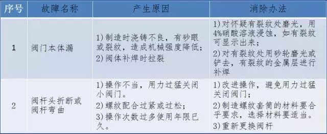
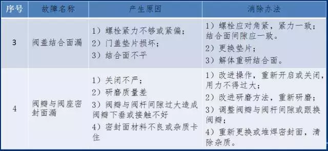
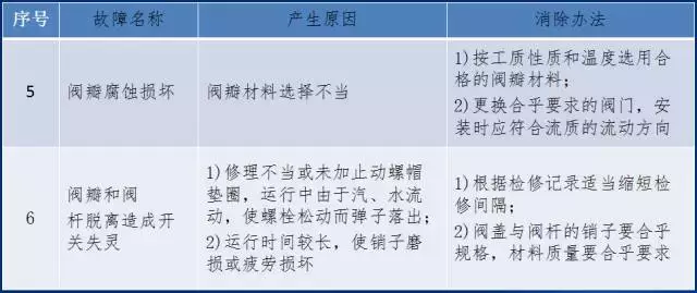
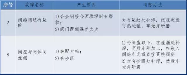
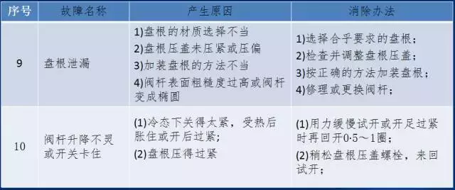
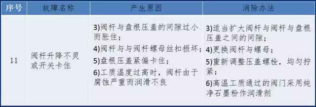
Common Globe Valve Failures