[Wuzhong Zhongchuang Control Valve] Sharing: Learning Control Valves, Valve Doctor Helps You Highlight the Key Points!
【Wuzhong Zhongchuang Control Valve】Control Valve = Actuator + Valve Body Components + Accessories
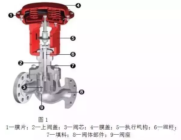
Among them, the actuator is the driving device of the control valve. It generates corresponding thrust according to the signal pressure, causing the push rod to produce corresponding displacement, thereby driving the valve core of the control valve to act; the valve body component is the regulating part of the control valve, which is in direct contact with the medium. Through the displacement of the actuator push rod, it changes the throttling area of the control valve to achieve the purpose of regulation.
Control valves are mainly divided into three categories according to their energy sources: pneumatic control valves, electric control valves, and hydraulic control valves. Their difference lies in the actuators they are equipped with. The former is equipped with a pneumatic actuator, the middle one is equipped with an electric actuator, and the latter is equipped with a hydraulic actuator.
Pneumatic Control Valve Cross-Section Structure Diagram
The Role and Importance of Control Valves in Systems
Control valves are indispensable in regulation systems. They are an important link in industrial automation systems and are known as the "hands and feet" of production process automation.
As shown in the figure below:
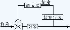
Figure 1-1 Composition of Automatic Regulation System
Functions of Control Valves
1. Regulation Function
1) Flow Characteristics
Flow characteristics reflect the relationship between the opening of the control valve and flow changes, to adapt to different system characteristic requirements. For example, flow regulation systems with fast response speed require logarithmic characteristics; temperature regulation systems with slow response speed require linear flow characteristics. Flow characteristics reflect the regulation quality of the control valve.
2) Adjustable Range R
The adjustable range reflects the flow range that the control valve can control, expressed as the ratio R = Qmax : Qmin. The larger R is, the wider the range of flow regulation and the better the performance indicators. Typically, the R of a valve is 30. For good valves, such as V-type ball valves and full-function ultra-light control valves, R can reach 100~200.
3) Small Opening Working Performance
Some valves are limited by their structure and have poor small opening working performance, resulting in jump-start and oscillation, and R becomes very small (i.e., Qmin is very large), such as double-seat valves and rubber-lined butterfly valves. Good valves should have fine-tuning capability at small openings, which can meet the regulation of very small flows while requiring stable operation. Such valves include V-type ball valves, eccentric rotary valves, and full-function ultra-light control valves.
4) Flow Coefficient Cv or Kv
The flow coefficient represents the flow capacity. For the same diameter, the larger the Kv value, the better. This is especially true for ball valves and butterfly valves, whose Cv/Kv values are 2~3 times those of single-seat valves, double-seat valves, and cage valves.
5) Regulation Speed
Meets the system's requirements for valve action speed.
2. Shut-off Function
The shut-off function is represented by the valve's leakage index. Shut-off usually refers to leakage less than 0.001%, which reflects the inherent quality of the valve. In valve applications, there are strong complaints about the large leakage of domestic valves.
3. Differential Pressure Overcoming Function
It is usually expressed by the allowable differential pressure when the valve is closed. The larger the allowable differential pressure, the better this function. If not properly considered, the valve plug will be pushed open by the differential pressure, causing the valve to fail to close in position and resulting in excessive leakage. Therefore, valve shut-off must overcome the working differential pressure when the valve closes.
4. Anti-blocking Function
For the regulation of unclean media or even clean media, welding slag and other debris in the pipeline may cause valve blockage or jamming. Therefore, the valve should have good anti-blocking function to ensure normal regulation. Valves with the best anti-blocking performance are single-seat angle valves with the simplest flow path and rotary valves, such as ball valves, butterfly valves, and eccentric valves; valves with complex flow paths, valves with upper and lower sleeve guidance, and labyrinth multi-stage pressure-reducing valves are prone to blockage and jamming.
5. Corrosion Resistance Function
Resist corrosion, erosion, and cavitation of the medium to improve the service life of the valve.Valve corrosion is a material corrosion problem caused by the chemical properties of the medium, which is usually solved by selecting corrosion-resistant materials; erosion is caused by high-speed flowing media and media containing particles. The solution is to select wear-resistant materials, such as overlay welding Stellite alloy or tungsten carbide. For cavitation, anti-cavitation measures must be adopted in the structural design. For high-pressure valves and control valves working with large pressure differentials, multi-stage pressure reduction forms should be adopted.
6. Pressure Resistance Function
It reflects the strength and indicators of the valve, that is, the medium cannot leak outward through the sealing area and defects in the valve body. During factory testing, 1.5 times the nominal pressure is usually used for inspection. For high-pressure media, forged structure is adopted; cast iron valves have the lowest pressure resistance strength, and cast steel valves should generally be selected.
7. Temperature Resistance Function
Meet the strength and performance of the valve under different temperature conditions. Large temperature changes will reduce the strength of the valve body material. Therefore, the valve must meet the requirements of the medium's temperature change range to ensure good strength at working temperature.
8. Appearance and Weight
Reflects the appearance quality of the valve and requires instrumentation, lightweight design, and miniaturization. Its weight should be as light as possible to facilitate use, such as lifting, installation, maintenance, etc.
Comparison of Functional Performance of Various Control Valves
Control Valve Performance Indicators
According to the national standard for pneumatic control valves: GB/T4213-92, there are a total of 14 performance indicators:
1 Basic error; 2 Hysteresis; 3 Dead zone; 4 Start and end point deviation; 5 Rated stroke deviation; 6 Leakage; 7 Sealing of packing gland and other connections; 8 Sealing of air chamber; 9 Pressure resistance; 10 Rated flow coefficient; 11 Inherent flow characteristics; 12 Vibration resistance; 13 Service life; 14 Appearance.
Requirements for Air Source and Ambient Temperature of Control Valves
The air source should be clean, dry air without obvious corrosive gases, solvents, or other liquids. For control valves with positioners, the amount of solid particles in the air source should be less than 0.1g/m³, and the particle diameter should be greater than 3μm, with oil content less than 1ppm.
Unclean air source for the positioner is the main cause of abnormal positioner operation, accounting for more than 2/3 of failures, and special attention should be paid to this point.
The ambient temperature for control valves is -25~+55℃ or -40~+70℃.
Control valves should meet the above requirements during operation.
Bellows Control Valve
When toxic, volatile or valuable fluids cannot be allowed to leak, in high vacuum applications or according to environmental clean air requirements (EPA, TA-Luft certification), as well as in special applications in nuclear industry, petrochemical and other fields, radial annular packing seals cannot be used, metal bellows seals are used to achieve "zero leakage" requirements.
Control valve bellows seal applies a bellows assembly, with its lower end usually welded and fixed to the valve stem, and the upper end fixed to the extension bonnet and compressed for sealing, providing an axially deformable metal isolation sleeve between the valve stem and the process medium inside the valve, forming a dynamic seal to achieve "zero leakage" at the valve stem, and the valve stem lifting action is frictionless. Auxiliary conventional valve stem packing backup is used as dual protection to prevent external leakage in case of bellows rupture or failure. Generally, a leakage detection port is designed, which can also be used to inject sealing liquid/isolation liquid if necessary, and a leakage switch/sensor can also be installed.
Metal bellows is an elastic, thin-walled, shell component with multiple transverse corrugations (hereinafter referred to as bellows), which can be made in single or multiple layers.
There are three manufacturing methods for bellows: mechanical forming, hydraulic forming, welding.
Bellows manufactured by mechanical forming methods have their corrugations continuously formed one by one on thin-walled metal tubes using rotating tools or dies, and can be made into single-layer or multi-layer bellows as needed. The tube material is generally cold-drawn thin-walled tubes (seamless tubes) made of stainless steel and thin-walled tubes formed by rolling and welding thin plates (welded tubes), which is also an important factor affecting the service life and performance of bellows. Bellows made from thin-walled tubes (welded tubes) produced by fusion welding of rolled strip or plate materials are significantly stronger than those made from seamless thin tubes (seamless tubes), with orders of magnitude difference in cycle life.
Bellows manufactured by hydraulic forming methods are produced by placing thin-walled metal tubes in a mold, applying hydraulic pressure from the inside, and simultaneously axially compressing the metal tube to create the bellows. The tube material selection is the same as for mechanical forming methods, also using cold-drawn thin-walled tubes and thin-walled tubes formed by rolling and welding thin plates. Bellows manufactured by welding methods are made by alternately welding the outer and inner edges of multiple annular elastic metal diaphragms together to form the bellows.
For mechanically formed U-shaped bellows, each corrugation occupies more spatial height than a single convolution of welded bellows, and under the same displacement (stroke), the length is much greater than that of welded bellows, approximately 3 times longer, requiring a longer extended bonnet. However, U-shaped corrugations do not easily retain process materials in the folded layers like welded bellows do, have greater strength, higher pressure resistance, and relatively longer cycle life.
At full stroke, working pressure and temperature, the cycle life of welded bellows seals is 10,000 cycles, with rated cycle life exceeding 100,000 cycles.
Main Performance of Bellows
1. Stiffness
The stiffness of a bellows is the force required to produce unit displacement of the bellows. Depending on the nature of load and displacement, there can be axial stiffness, bending stiffness, torsional stiffness, etc. In practical applications, axial stiffness is the most important. For axial stiffness, it is a parameter that reflects the sensitivity of the bellows; the greater the stiffness, the poorer the sensitivity. Axial stiffness is also inversely proportional to the number of corrugations.
2. Displacement
The displacement of a bellows is the sum of its compression displacement and extension displacement, and is proportional to the number of corrugations (single corrugation displacement multiplied by the total number of corrugations equals total displacement). There are two types: maximum displacement and allowable displacement. Maximum displacement refers to the maximum displacement that can be generated when the bellows, under external pressure, is compressed until the corrugations contact each other;
Allowable displacement refers to the maximum displacement that the bellows can achieve without producing specified plastic deformation. Under normal operating conditions, the working displacement that is generally allowed to occur is 40%-50% of the allowable displacement.
3. Pressure Resistance
Pressure resistance is divided into two forms: internal pressure and external pressure. Generally speaking, for the same bellows under otherwise identical conditions, stability under external pressure is better than under internal pressure, so the maximum pressure resistance under external pressure is higher than under internal pressure.
4. Cycle Life
The movement process of the bellows with the valve stem from fully open to fully closed and back to fully open is called a cycle. Cycle life refers to the maximum number of cycles the bellows can perform reciprocating motion without failure under specified pressure, temperature, and axial stroke. The cycle life of the same bellows is related to its working conditions, displacement magnitude, cycle frequency, pressure, and temperature. External force torsion, excessive displacement, and scratches or impacts during application seriously affect the cycle life and sealing effect.
The bellows is welded to the valve stem and positioned at 50% of the valve stroke when in a free relaxed state, so that the compression displacement and extension displacement are approximately equal, which can maximize the cycle life. Most regulating control valves typically operate within a small range between 25%-75% of stroke, producing smaller displacements near the bellows relaxation point rather than the entire working displacement of full stroke action, which can also significantly extend the service life of the bellows, meaning the actual number of cycles is longer than the rated cycle life given.
5. Operating Temperature
Operating temperature is also one of the main factors affecting bellows life. Different bellows have different applicable temperature ranges, but even within the required range, the closer it approaches the upper or lower limits of the range, the more it affects the number of uses.
Self-Operated Regulating Valve
Self-operated control valves do not require an external power source and rely solely on the energy of the controlled fluid to operate and maintain the controlled variable constant.
1. Self-operated regulating valves are further divided into direct-acting and indirect-acting types.
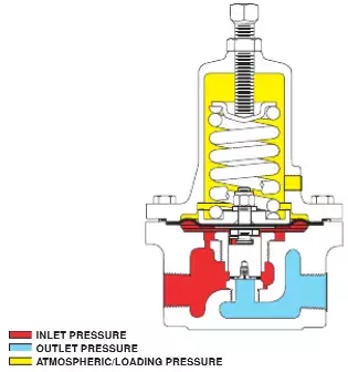
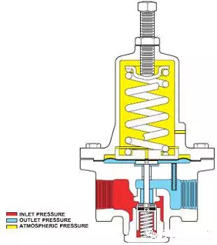
1) Direct-acting control valve Direct-acting control valve, also known as spring-loaded control valve, has elastic elements in its structure: such as springs, bellows, bellows-type thermal bulbs, etc., utilizing the principle of balancing elastic force with feedback signals. (Figure A, B, C)
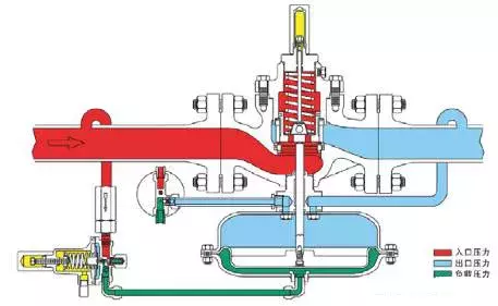
2) Indirect-acting control valve Indirect-acting control valve has an added pilot (pilot valve) which amplifies the feedback signal and then drives the main valve disc through the actuator to achieve the purpose of changing the valve opening.
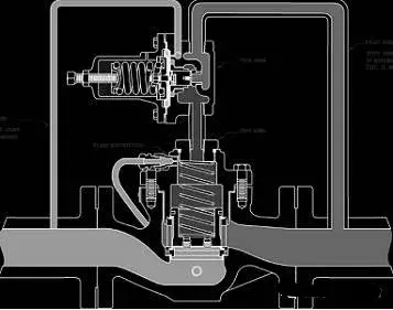
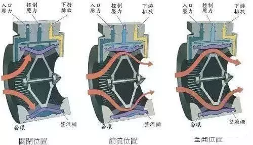
Axial flow self-operated valve
Nitrogen blanketing valve
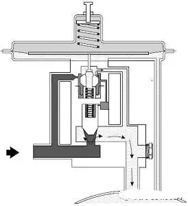
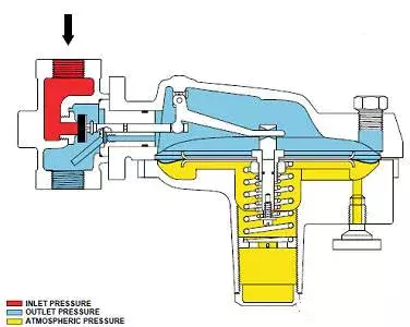
A type of self-operated pressure reducing valve, characterized by slightly positive downstream pressure (mbar).
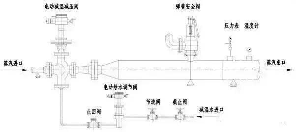
Desuperheater and pressure reducing station
Separate type: Simple structure, easy maintenance, low cost, suitable for low temperature and low pressure.
Integral type: Compact structure, high reliability, high control accuracy, suitable for high temperature and high pressure.